All of the following simulations were coded entirely in Java.
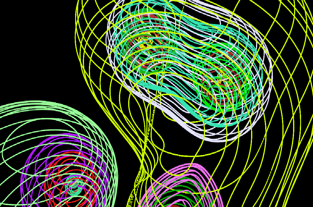
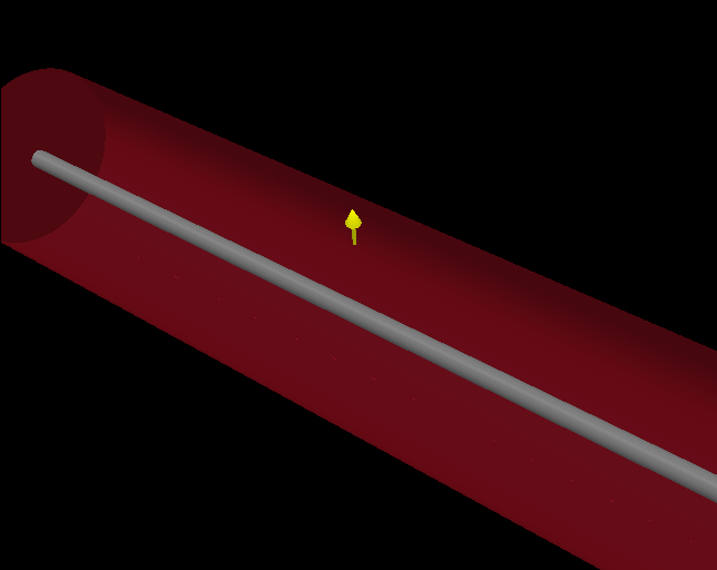
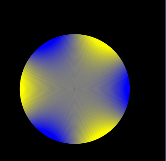
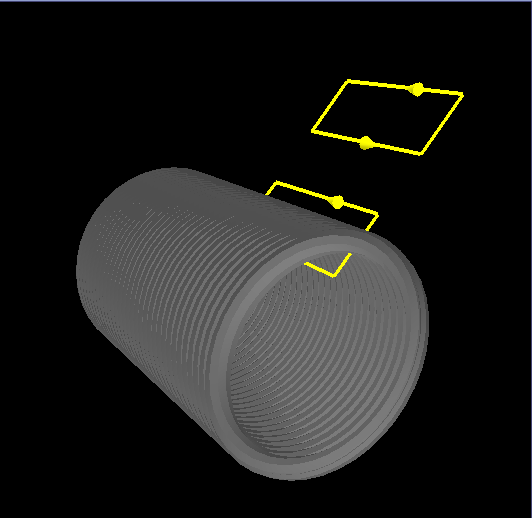
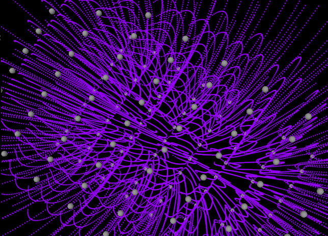
Simulations of the electric field due to a variety of charge configurations are presented and discussed. In addition to the classic textbook figures of the electric field due to a single charge, the field due to two like charges of equal magnitude, and the field due to two unlike charges of equal magnitude, simulations of the electric field due to each of the following configurations are presented and discussed: three like charges in a line, a line of like charges, a ring of like charges, a ring of like charges and a single charge outside the ring, a sheet of charges, and a sheet of positive charges and a sheet of negative charges.
The equipotential surfaces due to several charge configurations are presented.
A flux surface, a flux box, and the Gaussian surfaces for the following systems are presented and explained: a point charge, a long cylinder, a sphere, and an infinite charge sheet.
The potential due to each of the following systems is shown: a long rectangular pipe, a long cylindrical pipe, and sphere. Also, the electric field lines due to a grounded conducting sphere in an otherwise uniform field are plotted.
Amperian Loops are shown and explained for the following systems: long straight wires, infinite current sheet, and a solenoid.
Three types of motion are displayed: cyclotron, helical, and cycloidal.
Simulations of the magnetic field lines due to a variety of current-carrying wire configurations are presented and discussed: a long straight wire, two parallel wires, two anti-parallel wires, a row of parallel wires, a circular wire, Helmholtz coils, a toroid. These simulations all depict magnetic field lines that form closed loops or go off to infinity. Students are sometimes led to believe that this simple behavior is a necessary consequence of the divergence-free nature of magnetic fields. However, magnetic field lines can exhibit far more complicated behavior and the final two simulations- two perpendicular wires with a uniform magnetic field and a circular wire and a straight wire that lies along the axis of the circular wire- illustrate this fact.
For more information on magnetic field lines that do not close after a single loop, see the following references:
Simulations depicting a physical dipole, a pure dipole, a dipole in an otherwise uniform magnetic field, a uniformly magnetized sphere, and a uniformly magnetized cylinder are shown and discussed. A conceptual derivation is presented for the bound surface current density and the bound volume current density.
The three fundamental laws of geometric optics are illustrated. The difference between perpendicular and parallel polarization is also illustrated, and the Fresnel coefficients are plotted from normal incidence to grazing incidence, or to the critical angle, for several cases. The behavior of the electric and magnetic fields of the reflected and transmitted waves is gleaned from the Fresnel coefficients and is depicted vectorially. The reflectance and transmittance are also plotted. Also, Brewster's angle and the critical angle are explained and the behavior of the wave vectors is depicted vectorially.
The electric and magnetic field lines are shown and discussed for the following transverse electric modes and transverse magnetic mode: TE10, TE20, TE01, TE11, and TM11. In addition, the surface charge and surface currents induced on the inner surface of the waveguide are simulated for several modes.
Coming Soon---Dielectrics, Capacitors, the Divergence Theorem, Stokes' Theorem, and more!